Technological change has reached a furious pace in some parts of the manufacturing world. In other places, some traditional means of fabricating still hold out.
The reasons are familiar. Acquiring new technology may be viewed as cost-prohibitive for some companies. Others simply believe if the process is not broken, why bother to fix it.
Competitive realities are independent of checking accounts and inefficient fabricating practices, however. They have a tendency to hit companies in the face if they aren’t paying attention to the world around them.
That’s particularly true in pipe welding. The combination of experienced welders and the belief in tried-and-true methods of joining pipes has created an environment that hasn’t been quick to change. But if recent technology introductions made at the FABTECH® show in Chicago last November are any indication, pipe welders may be put in the position where they will have to seriously consider new welding technologies.
In the Field
The way that mainline pipe welding—the welding of long, straight sections of pipe that cross the countryside—is done in North America is fairly straightforward. Two sections of similarly sized pipes are brought together, and a pneumatic or hydraulic machine, typically on the inside, is used to clamp the two sections together to facilitate the welding. When connected, the pipes are J-beveled about 5 degrees to accommodate the on-site welding. (The pipes traditionally leave the pipe mill with a 30-degree bevel on their ends.) An external wire-fed welding bug is then used to lay quick and consistent beads all the way through the final pass.
This approach works well until you are required to join special sections of the pipe, which may have to clear a road or a river crossing, for example. These special sections are fabricated to the required length and then tied in to the main line that stops and starts again on either side of the crossing. You simply can’t use the internal clamping technology for these types of applications because if the brakes on these units were to fail, these large devices, some weighing up to 1,000 lbs., would come screaming down the pipe like a torpedo. In fact, these internal clamps are not used on inclines of more than 22.5 degrees. There’s no getting around the law of gravity.
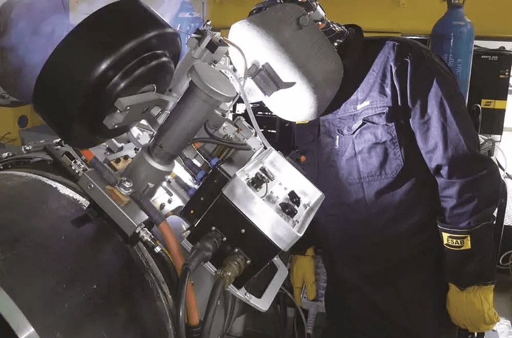
Gordon Eadie, global pipeline segment manager, ESAB Welding & Cutting Products, said that in these situations, manual welding is needed to complete the job. Welders not only have to be skilled enough to work in various vertical welding positions, but also at odd angles, like 30 or 60 degrees. Needless to say, that leaves some exasperated companies looking for some automation help. They have gotten a taste of what automated welding has done for mainline welding, so why wouldn’t they want something for these not-so-straight segments?
That led ESAB to develop the Pipeweld Orbiter, which consists of a lightweight bug and a fast-fit band that clamps on pipe with diameters greater than 8 in. (Pipe wall thickness, particularly for smaller-diameter pipe, will help to determine if mechanized welding makes sense for this type of application. For example, a welder using cellulosic electrodes for the root and hot passes on an 8-in.-diameter pipe with a wall thickness of 0.25 in. likely could finish off the fill and cap passes easily enough without the need for mechanized follow-up.) The bug contains the torch, drive mechanism, controls, wire spool holder, wire feed mechanism, cables, and hoses. It is designed to work with any constant-voltage welding power source that can provide sufficient output for the wire selected. For larger-diameter pipes, perhaps 16 in. or more, two bugs can be used at the same time on both sides to speed up the welding process.
Read more: New developments in modern pipe welding