Drilling Machine: It is a machine which is used to drill the holes on the components or workpiece with the help of drill bits.
The drill bits are also called as Multi-point cutting tools which can have their rapid impact on the Material Removal Rate (MRR) i.e. a single point cutting tool(like the one used in a lathe machine) can removes the material slowly whereas, a multi-point cutting tool removes the material at a faster rate and thereby increases MRR.
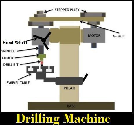
2.Construction of Drilling Machine:
The parts are as follows.
1.Base(Bed):
The base is made up of Cast Iron which has the capability of high compressive strength, good wear resistance and good absorbing capability(i.e. absorb the vibrations induced during working condition) and for these reasons, it acts as a base to the drilling machine.
2.Column: It is exactly placed at the center of the base which can act as a support for rotating the Swivel table and holding the power transmission system.
3.Swivel Table: It is attached to the column which can hold the machine vice in the grips and thereby, the workpiece is fixed in the machine vice to carry out the drilling operation.
The Swivel table can move up and down by means of rotational motion and can be locked to the column by means of locking nut.
4.Power Transmission system:
It consists of motor, stepped pulley, V-belt and the Spindle. The power transmission is explained in the working of the drilling machine.
5.Hand wheel:
By the rotation of hand-wheel, the spindle moves up and down in the vertical direction in order to give the necessary amount of feed to the work.
Here, the rotational motion is converted into linear motion by means of a Rack and Pinion mechanism which was explained below.
6.Chuck: It is used to hold the drill bit.
3.Working Principle of Drilling Machine:
When the power is given to the motor, the spindle rotates and thereby the stepped pulley attached to it also rotates. On the other end, one more stepped pulley is attached and that is inverted to increase or decrease the speed of the rotational motion.
Now, a V-belt is placed in between the stepped pulleys so as to drive the power transmission. Here a V-belt is used instead of a flat belt, in order to increase the power efficiency.
Now the drill bit also rotates which was placed in the chuck and which was in connection with the spindle. As the Pulleys rotates, the spindle also rotates which can rotate the drill bit.
Now, by the rotation of hand-wheel, the spindle moves up and down in the vertical direction in order to give the necessary amount of feed to the work and this drill bit is used to make the holes on the component placed in the machine vice.
4.Drive Mechanism of Drilling Machine: Rack and Pinion Mechanism
This drive mechanism is based on Rack and Pinion Mechanism.

When the hand-wheel is rotated, it is converting the rotational motion to the linear motion by means of rack and pinion.
The setup consists of Rack(has fine grooves), Pinion, Chuck and the Drill bit. The drill bit has placed in the chuck and the chuck is connected to rack and when the hand-wheel rotates, the Pinion is inserted in the grooves of Rack[shown in the below fig.] and thereby the rotational motion is converted to linear motion and as this mechanism is running by means of Rack and Pinion called as Rack and Pinion mechanism.
5.Types of Drilling Machines:
- Radial drilling machine
- Upright drilling machine
- Automatic drilling machine
- Multiple Spindle drilling machine
- Deep hole drilling machine
- Sensitive drilling machine
- Portable drilling machine
- Gang drilling machine
6.Radial Drilling Machine
Drilling Machine is to make circular holes on the components with the help of Drill bits. But, the purpose of the Radial Drilling Machine is used to drill the holes in the given radial distance and this will be used, when the component size is large in terms of height.
When the component is large, it cannot fit its structure in the Machine vice. Therefore, the component has to be placed on the ground and the Radial arm of the drilling machine has to be rotated w.r.t the component to do the operation.
The Angle of a Drill bit is 118 Degrees.
7.Working Principle of Radial Drilling Machine:
When the power supply is given, the spindle rotates which was in conjunction with the motor. The Radial arm is adjusted w.r.t the type of operation and height of the workpiece. The spindle is connected to the chuck and the drill bit is placed in between the jaws of the chuck. The Drill head is adjusted on to the workpiece and a suitable feed is given. Then the drill bit drives into the workpiece very easily.
Drive Mechanism: Rack and Pinion Mechanism
When the hand wheel is rotated, then the Pinion which is attached to the rack also rotates which can convert the rotary motion to the linear motion and the driving mechanism is called as Rack and Pinion mechanism.

8.Construction of Radial Drilling Machine:
The setup essentially consists of
- Base
- Column
- Radial Arm
- Motor for elevating the arm
- Elevating screw
- Guideways
- Motor for driving drill spindle
- Drill head
- Drill spindle
- Table
- Base: It is made up of Cast Iron which possesses high compressive strength and good wear resistance. The base is used to support the assembly of parts on it and also absorbs the vibrations induced by the machine parts.
- Column: It is exactly placed at one end of a bed which can act as a support for rotating the radial arm in 360 degrees.
- Radial Arm: It is the arm which is connected to Column. The Drill head is slided from one end to another end by the guideways.
- Motor: It is placed on the drill head for driving the work unit(Spindle of the Drill bit)
- Table: The machine vice is connected to a swivel table which can hold the workpiece for further operation.
- Flywheel or Hand wheel: It is connected to the spindle arrangement which is used to move up and down w.r.t. the workpiece.
- Drive Head: It generally consists of two levers which by varying can increase or decrease the speed of chuck.
- Chuck: One end of the chuck is connected to the spindle arrangement and another end is connected to the drill bit(tool).
- Tool-Drill bit: The drill bit is used to drill the holes on the specimens.
- Workpiece: It has to be fixed in the machine vice provided on the table.