It is a multi-point cutting tool machining operation used for removing a layer of material from the complete surface of the workpiece and it is also used for producing holes in the components.
- Machining of flat surfaces, Slots, pockets, keyways, and profile.
- The Surface finish achievable is (RA value in microns ):3.2
- The Cutting tools used are made up of HSS CARBIDE material.
- The Milling Machine can be performed by both conventional and CNC type.
1.Types of Milling Machines:
- Horizontal milling machine.
- Vertical milling machine.
- Plain milling machines.
- Ram type milling machine.
- Universal milling machine.
- Bed Type milling machine.
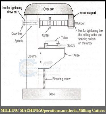
2.Horizontal Milling Machine Diagram:

3.Horizontal Milling Machine Parts:
Parts of the Horizontal Milling Machine are as follows.
- Base
- Column
- Knee
- Saddle
- Table
- Overarm
- Arbor Support and
- Elevating Screw.
4.Horizontal Milling Machine Working:
1.Base:
It provides support to all the parts of the machine and which can absorb the vibrations induced during milling operation and also acts as a reservoir for the cutting fluids.
2.Column:
The column is the main supporting frame mounted vertically on one side of the base which is box-shaped and has all the mechanisms inside it for the spindle and table feed.
3. Knee:
- The knee is a rigid casting mounted on the front face of the column.
- The knee moves vertically along the guideways and this movement adjusts the distance between the job mounted on the table and the cutter.
- This adjustment can be done manually or automatically by operating the elevating screw provided below the knee.
4. Saddle:
The saddle rests on the knee and it moves transversely, i.e., crosswise (in or out) on guideways provided on the knee.
5. Table:
The table made of cast iron rests in the saddle on guideways and provides support to the work.
The worktable and hence the job fitted on it is given motions in three directions:
a). Cross or transverse motion(in or out) provided by moving the saddle in relation to the knee.
b). Vertical movement (up and down) provided by raising or lowering the knee.
c). Longitudinal motion(back and forth) provided by hand wheel fitted on the side of the feed screw.
6. Overarm:
The Overarm is mounted at the top of the column and is the support for the arbor.
7. Arbor support:
The arbor is a machined shaft that holds and drives the cutters. The arbor support is fitted to the Overarm and can be clamped at any location. Its function is to support various arbors.
8. Elevating screw:
The upward movement and the downward movement to the knee and the table can be given by means of elevating screw which is operated either manually or Automatic.
5.Difference between Horizontal Milling Machine and Vertical Milling Machine:
In a horizontal milling machine, the axis of rotation of the spindle is horizontal to the table it is called a horizontal milling machine.
In a Vertical milling machine, the axis of rotation of the spindle is Perpendicular to the table called a Vertical milling machine.
In order to remove the material in the Milling Operations, the milling cutters will be used and are as follows.
6.Types of Milling Cutters:
There are two types of milling cutters.
1.End Milling Cutter
2.Peripheral Milling Cutter
3.Side Milling Cutter
4.Straddle Milling Cutter
5.Gang Milling Cutter

1.End Milling Cutter: If the cutting teeth are provided at the end face of the circular disc, it is called an End milling cutter. End mill cutter is used either with a vertical milling machine or by using drilling machine also.
2.Peripheral Mill Cutter: if the cutting teeth are provided around the periphery of a circular disc called as a peripheral milling cutter.
- It is used only with a horizontal milling machine.
- The peripheral milling cutter is mounted on the expandable shaft called Arbor.
3.Side Milling Cutter: In addition to the face, if the cutting teeth are provided on periphery also called as a Side Milling Cutter.
- If the peripheral milling cutter is superimposed on the end mill cutter called as side end mill cutter.
4. Straddle Milling Cutter: In addition to the periphery, if the cutting teeth are provided on faces also called aa s straddle milling cutter. i.e. End milling cutter is superimposed on to the peripheral milling cutter.
5.Gang Milling Cutter: If a gang of peripheral milling cutters of different sizes is kept together for removing the material simultaneously from one workpiece called a Gang Milling Cutter.
7.Types of Milling Operations:
They are two types of milling operations.
1.Face Milling Operation
2.Slot or Slab Milling Operation
3.End Milling Operation
4.Angular Milling Operation
5.Side and Face Milling Operation
6.Form Milling Operation
7.Slitting Operation
8.Keyway Milling Operation
9.Gear Cutting Operation
10.Profile Milling Operation
11.Helical Milling Operation
The detailed explanation for the different types of milling operations is as follows.
1.Face Milling Operations:
If the Milling Operation is used for removing a layer of material from a complete surface of the workpiece is called a face Milling Operations.
2.Slot/Slab Milling Operations:
If the Milling Operation is used for producing slots in the component is called a slab or slot Milling Operations.
In general, both the types of milling operations will be performed by using both the type of milling cutters but it is preferable to perform face Milling Operation with end mill cutter and slab Milling Operations with a peripheral milling cutter.
When peripheral milling cutter is used for performing the Milling Operation there are two methods of milling will be used.
3.End Milling Operation:
- By end mill cutter, we can perform End Milling Operation.
- For machining slots, pockets, keyway, etc
4.Angular Milling Operation:
- Angle milling cutter or fitting spindle head in vertical.
5.Side and Face Milling Operation:
- By side and face milling cutter we can perform this operation.
6.Form Milling Operation:
- By form milling cutter, we can perform this operation.
7.Slitting Operation:
- By the metal slit saw.
8.Keyway Milling Operation:
By plain milling cutter or end milling cutter, we can perform this operation.
9.Gear Cutting Operation:
- by using Formed tooth cutter with dividing head.
10.Profile Milling Operation:
By a ball nose cutter on CNC Milling machine (Both 3D and 2D profiles)
11.Helical Milling Operation:
Produces grooves and prosperity of cylindrical work.
8.Methods of Milling Operations:
There are of two methods.
1.Up Milling or Conventional Milling
2.Down Milling or Climb Milling.
Features:
In UP milling, the direction of movement of workpiece and direction of rotation of the tool is opposite whereas in down milling the directions are same.
In UP milling, because of the opposite direction, the forces, power consumption, and tool wear are high whereas tool life is low.
In case of down milling, because of the same direction, forces, power consumption, and tool wear are low and tool life is longer.
In UP milling, the thickness is varying from minimum at the beginning to the maximum towards the end whereas in Down Milling Operations the uncut chip thickness is varying from maximum at the beginning to the minimum towards the end.
Because of large uncut chip thickness at the end, the surface finish produced is poor in Up Milling whereas in Down Milling because of the small uncut chip thickness at the end, the surface finish is better.
In Up milling because of opposite direction, the tool is lifting the workpiece upwards, therefore strong work holding devices are required whereas in Down milling because of the same direction, forces are less and strong holding devices are not required.
Therefore based on the above, it is preferable to use the Down milling.
9.Units and Formulas of Milling Machine:
Measurement units are
FPT = Feed Per Tooth
d = Depth of Cut
IPM = Inches Per Minute
DIA = Diameter
F = Feed Inn Inches or mm per minute (F)
FPR = Feed Per Revolution
RPM = Revolution Per Minute
L = Length of Cut
W = Width of Cut
MMPR = Millimeters Per Revolution
MRR = Metal Removal Rate
SFM = Surface Feed Per Minute
T = Number of Teeth(Milling Cutter)
TCs = Time Cutting in Seconds
SMPM = Surface Meters Per Minute
TPI = Thread Per Inch
TCm = Time Cutting in Minutes
IPR = Inches Per Revolution
Formulas of Milling Machine:
SFM (Surface Feed Per Minute) = 0.262 X DIA X RPM
Cutting Speed
RPM (Revolution Per Minute) = 3.82 X SFM ÷ DIA
IPM (Inches Per Minute) = FPT ÷ (RPM X T)
Feed Per Tooth
MRR (Metal Removal Rate) = W x d x F
FPR (Feed Per Revolution) = IPR ÷ RPM
FPT (Feed Per Tooth) = IPM ÷ (RPM x T)
SMPM (Surface Meters Per Minute) = SFM x 03048
Converting SFM To SMPM
IPR (Inches Per Revolution) = IPM ÷ RPM
Converting IPM To IPR
L (Length of Cut) = IPM x TCm
Distance Over Time
TCm (Time Cutting in Minutes) = L ÷ IPM
Time Cutting Over Distance In Minute
TCs (Time Cutting in Seconds) = L ÷ IPM x 60
Time Cutting Over Distance In Seconds
MMPR (Millimeters Per Revolution) = IPR x 25.40
Converting IPR To MMPR