A young entrepreneur invests his savings in a new trash-hauling business. He buys a new garbage truck and decks it out with his name, number, and a fancy new logo. He cleans it up for an afternoon photo shoot, and while reviewing the pictures he notices a rusty stream making its way down the side of the fancy new logo. Upon further investigation, he finds the moisture is seeping from a single pore of
AWS A3.0 – Welding Terms and Definitions defines porosity as “cavity-type discontinuities formed in weld metal by gas entrapment during solidification…” Acceptance criteria for porosity in codes we may be familiar with can look like this:
AWS D1.1: Porosity shall not exceed 3/8 in. in any linear inch of weld, and shall not exceed ¾ in. in any 12-in. length.
ASME B31.1: Porosity cannot have dimensions greater than 3⁄16 in.
API 1104: Porosity cannot exceed 1/8 in. dia.
Reading those acceptance criteria leads me to believe that the codes we build to are a lot more forgiving when it comes to porosity than the quality assurance departments that enforce them.
Porosity has developed a bad reputation in that just the mere mention of it makes welders want to take drastic action to remove or eliminate it. Certainly, there are situations where that is necessary, but in others, the presence of porosity can range from being a cosmetic nuisance to a potential benefit.
What Causes Porosity?
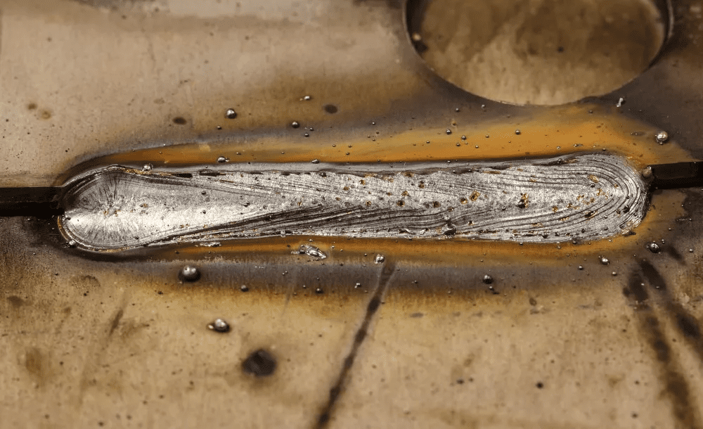
So, what causes porosity? Simply put, porosity occurs when nitrogen, oxygen, or hydrogen becomes trapped inside the molten weld pool as it solidifies. Those gases either leave a subsurface void or they leave a pore that is visible at the surface.
1. Porosity caused by nitrogen or oxygen. This type of porosity mainly is due to inadequate shielding gas coverage. There are many reasons for inadequate shielding gas coverage:
Shielding gas flow rate is too low. Welding completed to a weld procedure specification (WPS) requires that the shielding gas flow rate fall within a specific range. Make sure the flow rate range is appropriate, taking into consideration environmental conditions like wind speed.
If the shielding gas flow rate is set correctly, but it measures too low at the nozzle, the delivery system may be to blame. The delivery system for shielding gas comprises components joined together and sealed with sealants and O-rings at each of the several connections. Seal failure leads to low flow rates at the nozzle and/or nitrogen and oxygen being drawn into the delivery system, reducing the shielding at the weld.
Shielding gas flow rate is too high. With shielding gas, more is not always better. Excessive flow rates at the nozzle will generate turbulence that draws nitrogen and oxygen into the area of the weld pool, changing the shielding mixture, resulting in porosity.
Read more: The facts about weld porosity