Tips for choosing cutting tools, toolpaths and machines wisely
Stainless steel is far from an unknown quantity in machine shops. Yet, particularly in automotive and aerospace applications, tools and cutting methods continually evolve to optimize output—particularly as parts get more complex.
Take aerospace components. A bracket that might have been a separate component is likely to be incorporated into a larger part, requiring more machine precision and flexibility.
For popular grades like precipitated hardened 15-5 and 17-4, machine builders and toolmakers continue to innovate machining options. Learning how to machine stainless steel continues to evolve.
Machine Tool Musts
Besides the correct tooling and the right speeds and feeds, shops need heavy and well-built machines with quality components and a solid casting foundation, said Mike Cope, product technical specialist for Hurco Companies, Indianapolis.
“Machining stainless steel can be tough, so components that help ensure rigidity are key pieces to the puzzle—things like solid box or roller ways instead of simple linear ways on all linear axes and large, robust ballscrews to hold the table in position during cutting,” Cope said.
A powerful spindle is also key, he added. “Machines with adequate horsepower and ample torque will provide much better results when cutting stainless and will also help the machine last longer. Lighter-duty machines can have success when cutting stainless, but if the machine is tasked with cutting it often, then a machine with the right components will provide better results and more longevity. CAT 50 or BIG Plus dual-contact spindles can be helpful as well.”
Motion control systems are also critical, particularly for optimum surface finish and, to some degree, part tolerance.
“For a good surface finish, you need smooth motion,” Cope explained. “Features such as toolpath tolerance, smoothing, and NC block lookahead are very important. NC block lookahead will determine how far into the upcoming moves the control will begin to prepare itself for smooth motion, and toolpath tolerance and data smoothing options can be controlled within the NC program to affect speed and surface finish. These settings can be opened up to allow for faster motion when roughing or semi-finishing, and then tightened for finishing. Mixing the settings will help cut cycle times when roughing and still provide the control necessary to produce good surface finishes and tolerances.”
Hurco’s motion system has dynamic variable lookahead up to 10,000 blocks, Cope continued, “which means the motion system is smart enough to do the adjustments for you, depending upon the toolpath. Hurco made UltiMotion standard on all machining centers sold in North America because motion control is critical to surface finish, reducing cycle times, and longevity of the CNC machine’s key components.”

Mitsui Seiki’s Wayne Wentworth stands in the work area of a five-axis Mitsui Seiki trunnion machining center. The table was custom engineered to accommodate a 78″ (198-cm) diameter part.
Mark Gilmore, technical product specialist for Takumi USA-CNC Machine Tools, Indianapolis, echoed the importance of rigid machine design and vertical mill construction to maintain tight tolerances with hardened stainless grades. “While being designed to absorb or isolate the vibration of cutting forces, they must also have the ability to accelerate and maintain speeds required to utilize the cutting tools and toolpaths of today without increasing costs by using high-priced servo motors and drives. The development of roller-type linear rails is replacing box way designs to achieve rigidity and speed and increase accuracy and surface finish.”
Over the past few years, explained Matt Gifford, aerospace structures product specialist at Mitsui Seiki USA Inc., Franklin Lakes, N.J., “you’ve seen what the industry calls high-efficiency milling. Instead of large stepover cuts, they’re taking lighter radial depth of cuts and larger axial cuts and going much faster.”
Tooling Tames Stainless
Tooling for cutting stainless steel must resist high heat, excessive cutting edge buildup and wear. Additives like sulfur can improve machinability “but cannot eliminate the challenges completely,” cautioned Hurco’s Cope. “These additives aren’t allowed in some of the tougher grades of stainless to machine, such as 304 and 316.”
Tools with more cutting flutes of course allow higher feed rates and more metal removal. “However, chip evacuation is also an important consideration,” Cope added. “Traditionally, we see five- to seven-flute cutters for roughing, and a much higher number of flutes for finishing. These are often solid-carbide cutters, but there are many suitable selections of inserted cutters.”
According to Dan Tucker, product manager, Western U.S. for Sandvik Coromant, Fair Lawn, N.J., the company’s more recent technologies, such as Inveio and Zertivo, have improved durability and prolonged insert edge integrity for greater tool life when machining stainless steels.
Zertivo features improved adhesion between substrate and coating and optimized cutting edge integrity, the company said; GC2334 grades are optimized for indexable drilling in stainless steel.
The Sandvik Coromant M612 is a face milling cutter developed to machine stainless steel turbo exhaust housings. The positive geometry and edge-line quality ensure reliable performance and an increased number of components per insert, according to the company.
Meanwhile, Inveio’s “tightly packed, uni-directional crystals create a strong barrier towards the cutting zone and chip. This greatly improves crater wear and flank wear resistance.” Furthermore, “heat is more rapidly led away from the cutting zone, helping the cutting edge stay in shape for longer times in the cut.” GC2220 grades optimize stainless steel turning in stable conditions.
“A commonality among all these materials is that the cutting edges are exposed to a great deal of heat, notch wear and built-up edge,” Tucker explained. “Large positive rake angle and clearance is a must,” as is insert geometry that gives minimum contact and friction between the chip and chip face.
Because stainless steel can build up on the insert, “we use sharper—more positive—rake angles on the top surface of the insert than we would use for materials like steel or iron, where we choose stronger geometries,” added John Pusatera, training specialist at Sandvik Coromant. “It is like using a sharp knife as opposed to using something that has an edge prep for strength. Having a more positive clearance helps make the tool sharper.”
For roughing, Tucker advised, “cutting edges should have the smallest possible reinforcement land on the edge.” Machine shops should “employ large cutting depths and feed rates in combination with lower cutting speed, rather than low depths and higher speeds.”
And for semi-finishing, “there should be sufficient material left for finishing to allow the tool to go beyond the deformation-hardening zone. Avoid excessive flank wear; this leads to a dull cutting edge, creating a work hardening zone.”
For finishing, “employ climb milling and avoid interruptions, if possible. Use a larger lead angle, if possible, and only use cutting fluid if running at lower cutting speeds.” Typical speeds range from 590-1,300 sfm (180-396 m/min).
Sandvik Coromant expects to release new ISO S stainless steel grades in the near future. ISO S refers to heat-resistant superalloy materials, “which in some cases we treat just like machining stainless steel,” Pusatera said. “This usually refers to using PVD-coated tools for added sharpness as opposed to using CVD-coated.”
According to Scott Lawrence, an aerospace specialist with Seco Tools LLC, Troy, Mich., “we have had success with lighter-side milling cutter paths, such as dynamic milling,” when optimizing toolpaths for stainless steels. “Best results are achieved by maximizing the tool’s flute length combined with the correct radial engagement. This eases spindle load, as well as fixturing, with these types of cutter paths; that seems to work well in extending tool life.” He also advised “picking the right-size tool to ensure chip evacuation, employing radius compensation in corners to avoid chatter and adjusting stepover based on axial length of cut.”
Some machine tool companies, he added, have options to check tool wear on the machine, “helping smooth machining and prevent work hardening. Additionally, by collaborating with our industrial partner Fusion Coolant Systems (which offers a supercritical CO2 minimum quantity lubrication and coolant system), we’re driving more effective cooling, increasing performance and optimizing productivity.”

Seco’s Jetstream Tooling controls heat and manages chips, preventing hazardous production-stalling tangles while doing away with the hoses and connectors generally required for coolant-through tooling.
At Mitsui Seiki, cutting tool development trials with heat-treated 15-5 achieved material removal rates of about 42 in3 (688 cm3) per minute while maintaining superior edge life—without coolant.
“Heat-treated 15-5 is not quite as gummy, so we were able to get chips to come off the cutting tools better,” Gifford noted, whereas 17-4 “tends to be more abrasive on the cutting tool, so it wears your edge a bit faster.”
When cutting stainless steels, coolant may not be the right choice, he added. “I’ve found the coatings on the cutting tool like heat; they have a better lubrication effect as they heat up.” That’s why he tends to recommend machining most 15-5 grades dry, especially when the insert tool is present. Under those conditions, tools have a tendency to crack when subjected to high heat and quick cooling. “Using an air blast to blow chips out of way so you’re not recutting the chips maintains temperature within the tool and is more stable for the process.”
To reduce cycle time and handle increasing amounts of toolpath data, Takumi’s Gilmore noted a pair of solutions.
“While all CAM systems can create HEM (high-efficiency milling) toolpaths that may reduce overall part cycle time, few are ideally optimized to achieve the quickest cycle time while eliminating destructive high cutting tool load,” he explained. “VERICUT software from CG Tech has proven technology that reduces the time to remove large amounts of material with HEM. We witnessed a 25 percent decrease in cycle time in stainless steel by VERICUT processing the toolpath created in CAM software on the Takumi H10 mill.”
As toolpath sizes generated by CAM systems increase, the ability to process large amounts of data on CNCs is vital. “FANUC will soon introduce the 0i-MF Plus control, with larger memory and high-speed capabilities now standard instead of optional,” Gilmore said. “This upgrade will increase the throughput of their basic control package, along with keeping costs low. Known for its reliability, the FANUC 0i-MF Plus control will unlock the potential of many CNC milling machines.”
Aerospace Applications for Stainless Grades
The composition of stainless grades like the 15 percent chromium and 5 percent nickel content in 15-5 PH is what makes machining a challenge, said Mark Francis, staff engineer for toolmaker Kennametal Inc., Pittsburgh. “The aerospace industry continually seeks to make lighter, stronger, better performing parts—faster and more efficiently—and machining operations must continually advance to support this drive,” Francis noted. “Stainless steel flap tracks are an example of aero components that our tools and expertise helped bring to fruition. The manufacturer wanted to use a specific stainless steel that would deliver strength and weight savings—with the added advantage of being virtually maintenance-free over the life of the aircraft.”
However, because of the alloying elements in the material, this stainless steel is more difficult to machine, he continued. Instead of wearing, the material gets harder over time. The material can work harden during machining, which contributes to tool wear and failure.
“Kennametal worked with the material manufacturer and the aircraft manufacturer to identify the best insert grades and cutting tools for the job and then defined best practices for machining the components from a forging.”

Prismatic workpieces such as this helicopter rotor hub are typical work for Mitsui Seiki’s large five-axis machining centers.
What makes PH stainless steel alloys relatively tough to machine, Francis explained, is “the high-strength material matrix and an average UTS (ultimate tensile strength) of 200 ksi/1,379 Mpa. If there is forging scale to cut though, the challenge is greater. The scale is very abrasive and can cause depth-of-cut notching. Depending on part shape and complexity, it is sometimes possible to use a high feed or copy mill (round inserts) to remove the scale prior to heavy machining.”
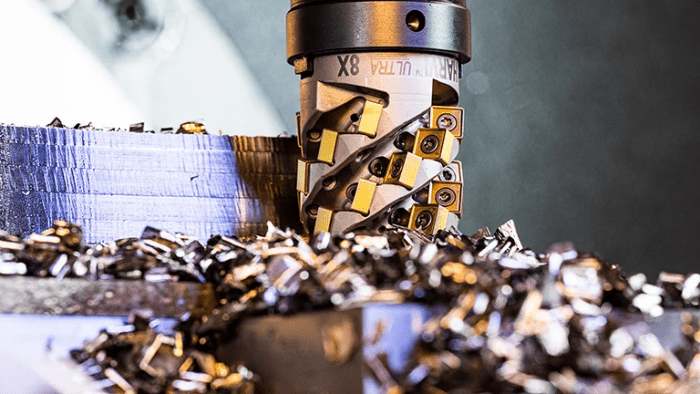
Kennametal offers tough carbide grades like KCSM40 and KCPM40 for roughing operations to resist thermal cracking and prevent premature chipping. Pairing those with the company’s KSRM face mills with round inserts allows for scale removal and complex feature machining. Meanwhile, Kennametal’s HARVI Ultra 8X indexable helical cutter with eight cutting edges per insert provides high metal removal rates, insert edge life economy, and reliability, Francis said.
“Kennametal flat-bottom drills are suited to a variety of applications with pockets or hard-to-reach areas and enable the user to create a hole to provide access for other tools to complete the machining process,” he said.
And for finishing, Kennametal’s HARVI III line of solid-carbide end mills is designed for aerospace materials to provide “excellent surface finishes at very productive feed rates and deliver outstanding tool life,” said Francis. “The carbide grade, KCSM15, provides the toughness and reliability expected in aerospace part roughing and finishing.”
The choice of machine tools for aerospace parts is changing, according to Gifford. Mitsui Seiki’s horizontal machine centers run from 630 mm to 2.5 m and produce everything from actuator housings and latch-type components to larger parts like flap tracks for wings. “Over 1 m is where we really have seen a large increase as parts have become more complex,” Gifford said. Parts previously suited for a 630-mm machine have been “meshed with another part and another part, and now it’s a much larger structural piece that has to be machined.”
The company builds its box way machines to remain rigid and robust to handle the types of cuts needed, he said. “We can turn the rpm up and take lighter cuts fast, say for finishing,” he said. “But for roughing, we have a big, robust spindle and castings that provide a rigid machine that can take the larger depth of cut and remove material at higher rates.”
Stainless Steels Gain Ground in Auto Applications
A Seco Tools project illustrates how stainless steels are gaining ground in automotive applications under the right circumstances.
“We are currently working with a major automotive OEM on a small-engine turbo manifold flange produced from a 17-4 cast stainless steel,” Lawrence explained. “Machining characteristics and makeup are close to a 310 stainless. Previous applications for these were cast iron, but due to [the need to] withstand heating cycles, stainless steel seems to handle expansion and contraction better.”
Machining this component in cast iron would normally have its limitations, he continued, but stainless steel “has added to the demand to hold tolerance and tool life. Mounting surfaces, such as gasket surfaces with higher finish requirements, are the most demanding due to interrupted cutting of cast irregularities. With this current customer, we were able to provide extensive finish requirement testing in our corporate headquarters lab, using our tooling, to ensure we can provide tool life and hold the needed tolerance.”
In instances such as this, high-feed milling and dynamic milling provided the best removal rate without putting stress on the machine or part, Lawrence added. “With good software, it’s easy to achieve part tolerances.”

Optimized roughing with Seco’s Niagara Cutter multi-flute end mill. The tool is designed for chip control in applications requiring depths of cut up to 3X tool diameter.
Noting the differences between automotive and aerospace applications for stainless steel, he said, “automotive, at least in my area, seems to be seen differently when it comes to machining. The automotive market is more driving on the CPU, which is driven from cost per edge of the cutting tool, as well as ease of use for machine operators, and eliminating tool handling by the operators. It comes down to what is the cheapest tool that can complete the required operation.”
But for aerospace, the cost of components and materials used “require different approaches,” said Atul Sharma, aerospace specialist for Seco Tools Canada. “Quality, security and reliability of the tool is paramount. Security and peace of mind [that there will be] no tool failures, and holding tolerance per part, are more of a concern. Rotating an insert edge, or tool edge, is cheaper than risking damage to a part.”
Positive chip breakers, Duratomic coating, chip splitters and wiper inserts help achieve better finish and productivity, he added.
In fact, most parts today are closer to near net shape and are usually accompanied by a model to help with programming. “Newer software seems to account for these features and allows the programming to select the fastest way to remove material,” said Sharma. “This includes dynamic milling areas on a part that would otherwise require cutting air in a standard toolpath. I have seen newer machine control software in aerospace accounts that allows the operator to download a model to a USB, upload it to the machine, and select machining strategies from the floor, using the machine controls.”